Hardware
First things first, I needed to get the gauges. I do not live close enough to my parents to be able to swing by and pick them up. I asked my sister, who lives 5 minutes away from them, to try to smuggle 3 gauges out of the basement without my Dad knowing. Fortunately she was able to find 3 gauges and mail them to me.

In the meantime I ordered the Arduino and Real-Time clock along with some other components I did not have on hand. I used a SainSmart Nano v3.0 Compatible with Arduino
for the smaller footprint and a SB4 Snappable PC BreadBoard Scored PCB
which matches a mini breadboard for soldering the components onto. I used the SwitchDoc Labs DS3231, AT24C32 EPROM, Battery
with a rechargeable LIR2032 battery because the Amazon reviews for the one listed in show notes said it came without the rechargeable battery.
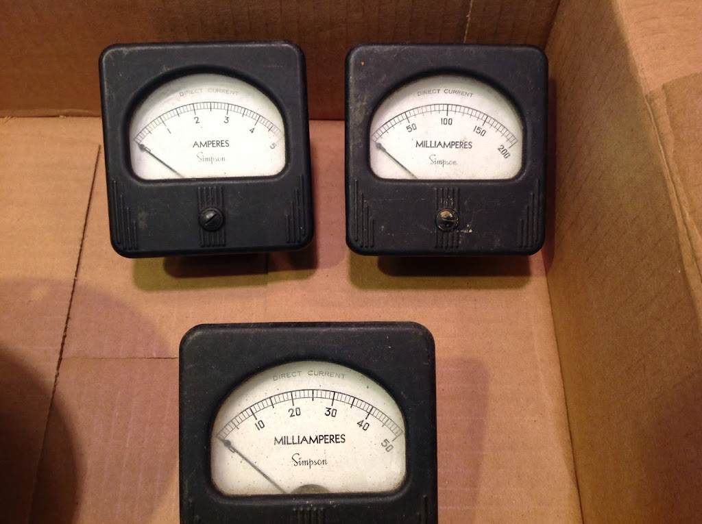
Each of the ampere gauges had a different scale which was perfect to be able to differentiate them. I had to modify them so they would work with .1 milli amp. I did this by taking them apart and removing the resister across the positive and negative terminals. The 5 Amp gauge in the picture below and to the left had a solid wire and the 50 & 200 Milliampere gauge had a coil like what you see in the picture to the right.


These meters are old so I did not want to replace the face or alter the face. I used the 5, 50, and 200 scales on the gauges for hours, minutes, and seconds respectively. I could not figure out an unobtrusive way to indicate the quarter marks while preserving the 60s/70s look of the meters so I decided to leave them alone.
Circuit
The following is the schematic used for the circuit. I added a Calibration indicator LED to identify when the Clock is in Calibration mode. I also added 2 switches. The first to adjust for Daylight Savings Time instead of pushing the Hour Set button to cycle through the time in the Fall. The second switch will allow the clock to change from Smooth movement to a Ticking movement. The original code had the clock using a smooth movement. Since I was not changing the faces of the gauges, I thought the ticking movement may help in determining time.

I tested the hardware by assembling it on prototype mini-breadboards. I tried to lay it out as it would be mounted on the PC boards. This helped figure out placement prior to soldering the components.

Software
I downloaded the software from Coding 101 Episode 56 – Embedded Programming 3/4. I also downloaded the Time Library and the Real Time Clock Library which I installed in my library directory under my Arduino project folder according to the Manual Arduino Library installation instructions. I tested the circuit with the code as provided to make sure everything was working.
The Analog Clock program uses 240 ticks of the 255 possible values PWM provides. This makes it easy to divide the hours, minutes, and seconds into uniform segments. 20 ticks make up a full Hour and 4 ticks make up a full Minute & Second. The program as provided has a nice feature to smoothly move the gauge between values. The seconds will move forward 1 tick every quarter of a second. The minutes will move forward 1 tick every 15 seconds. The hour will move forward 1 tick every 3 minutes. The clock also provides a calibration mode to adjust the trim pot so the clock takes advantage of the full scale of the meter. Do this after setting the min value to zero using the set screw on the front of the meter. The clock also uses 2 buttons to set hour and minute.
Once that was working, I decided to make some changes. First I implied the setup by initializing the Pull Up restisters in 1 step by using INPUT_PULLUP instead of the 2 step process of pinMode followed with digitalWrite. Then I moved the pins around so the PWM Analog Meter pins are together at 9-11, the Button & Switch inputs are together at 2-6, and indicator LEDs together at 12-13. I added an LED on pin 12 to indicate when the clock was in calibration mode.
I added a Daylight Savings Time (DST) switch to easily move the hour forwards or backwards. The switch is attached to pin 5. The Real Time Clock (RTC) is not effected by DST changes. I only modify the display on the gauge for DST. This time change is achieved by optionally adding 3600 seconds (number of seconds in an hour) to the time read from the RTC. I also adjusted the hour set process to remove the hour if the DST is active when storing the time in the RTC.
Since I am using gauges that do not use a scale easily aligned to 12 or 60, I was thinking it may be better to provide the option of staying on the hour, minute, or second until it changes. I added a switch to pin 6 to allow the clock to change between smooth or ticking motion.
See the code on GitHub at: https://github.com/greggubben/AnalogClock
Box
I build the wooden box out of Oak. The front face is 15″ across, 5 1/2″ high, and the sides are 6″ deep. The sides are made of 1/4″ thick oak boards and 5 1/2″ high. The base and top are made of 3/4″ oak. For the back I used plexiglass so the internals could be seen.


I mitered the corners of the sides and used 3/4″ square pine for attaching the sides together and attaching the sides to the base & top. The mounts are glued and nailed from inside. The nails are only used to hold it together until the glue sets. The top will be attached to the base with 1 1/4″ wood screws through the mounts.


The box was stained with a Dark Walnut wood stain. The inside has a Satin finish while the outside has a Gloss finish.
Final Assembly
The circuit boards are mounted to the base with enough wire to allow the components to be hooked up prior to installation. The buttons and switches are attached to the circuit board with 2 pin female headers. The USB Mini-B power cable is looped through the nylon spacers under the Arduino so the cable does not tug directly on the Arduino.

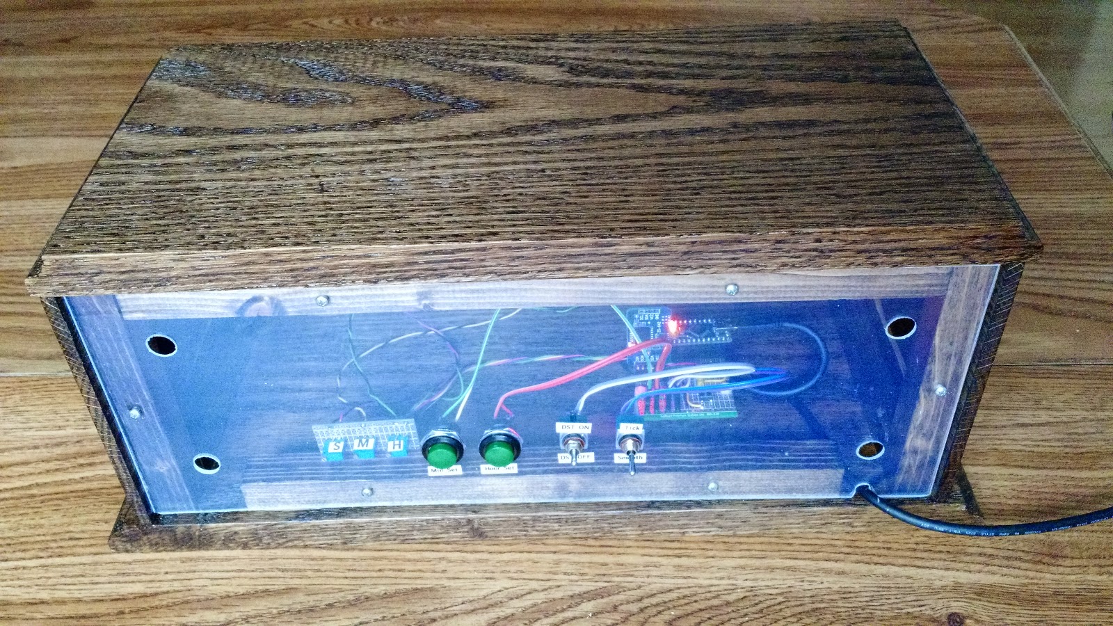
Below is the final assembly of the Arduino Analog Clock.
Front

Back
Credits
First shared on Know How and Coding 101 on the TWIT.tv network.
- Check out the following episodes for the coding:
- Check out the following episodes for the hardware:
Thanks to Fr. Robert Ballecer, SJ and Mark Smith.
Components
A few things to note:
- The SainSmart Arduino Nano uses a Mini-B USB connector not a Micro USB connector.
- I bought an assortment of trim pots for a few dollars more than what the show notes referenced so I would have few on hand for other projects.
- I also bought an assortment of nylon spaces for this as well as other future projects.
- I do not like soldering components like the Arduino and DS3231 directly to the board so I bought some female headers to plug them into.